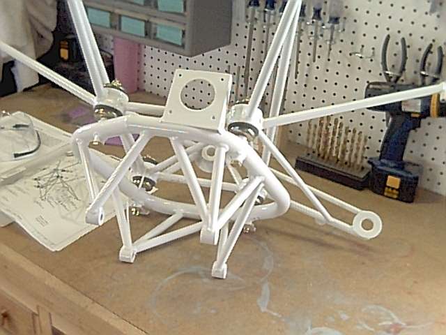
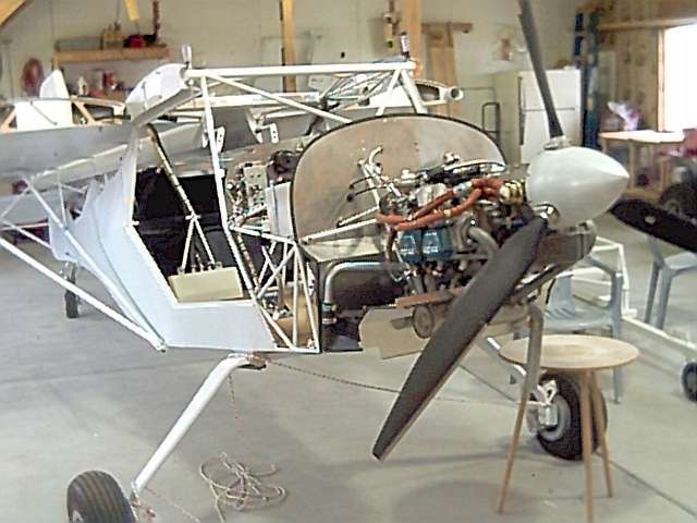
The Rotax 912 engine gets bolted to the engine mount, which in turn gets bolted to the fuselage. After I uncrated the engine, I had to partially disassemble the engine to attach this thing! The carbs were removed, the water pump housing was removed, and ignition wires were removed. The back of the engine was then bolted to the four attach points.
Cooling System
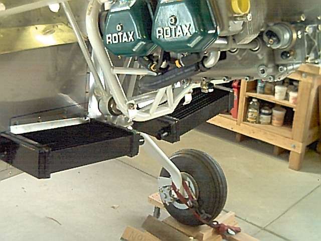
The engine is water cooled at each cylinder head and air cooled on the cylinder wall. Heat is dissipated through a pair of radiators which mounted to the firewall and were plumbed into the system. Two radiators were used to get the proper heat transfer and still fit into the round cowl.
Cabin Heater
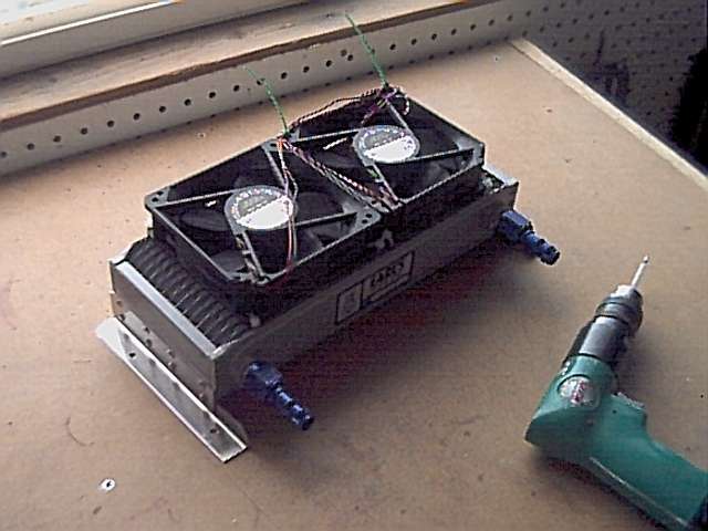
Cabin heat is provided similar to an automobile. Hot coolant is routed through a heater core (small radiator) and air is blown across. In the Kitfox, this was done by mating two small electric fans with the heat exchanger. This unit is mounted inside the cockpit under the instrument panel.
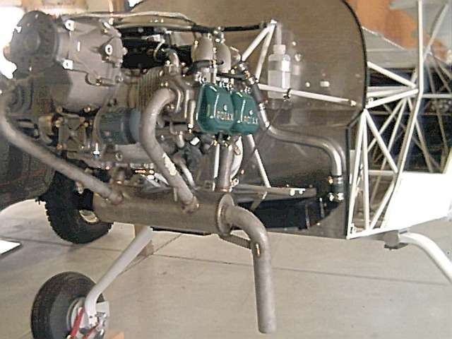
Exhaust System
The exhaust pipes were mounted on each cylinder and routed to a common muffler. The exhaust exits the cowl through the pipe out the bottom.
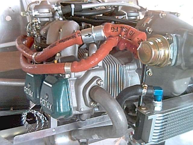
Oil System
The oil tank was mounted external to the engine. Lines were then run to the oil pump and the engine scavenge point.
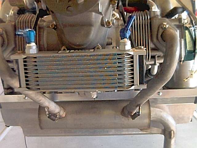
Oil Cooler
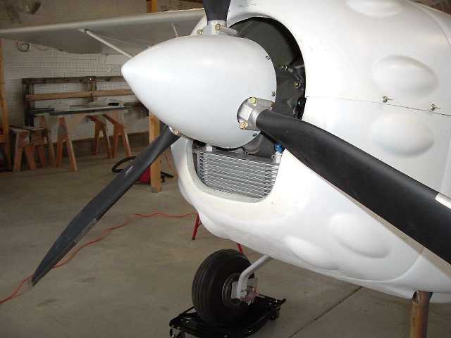
The oil gets cooled in a small radiator mounted to the front of the engine. It looks alot like the cabin heater radiator, doesn't it? Well, it is virtually the same. Both are off the shelf parts from Earl's Auto Supply. A difficulty that I encountered was when I tried to get the Rotax oil hose to fit on the AN fittings on the cooler. Rotax uses an 11mm hose. It would not fit, so I had to purchase some MIL 6000 hose instead.
The Rotax 912 uses two carbs. Fuel hose (protected by firesleeve) was routed from the firewall to the fuel pump at the front of the engine. Then, hoses were routed to each carb.
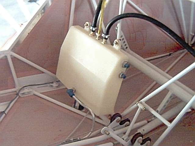
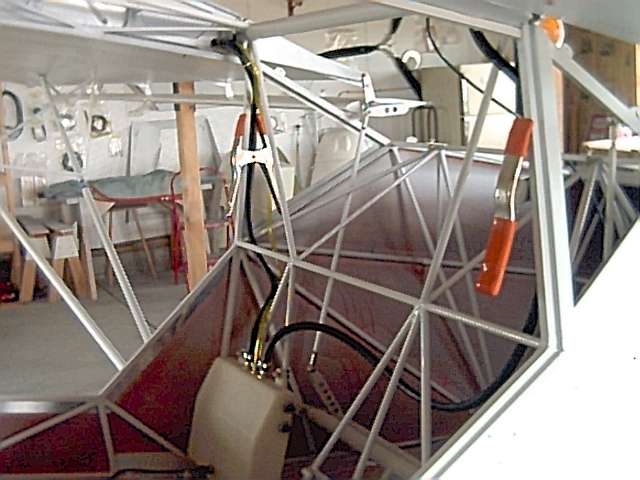
Fuel gets delivered from both wing tanks to a header tank (located behind the passenger seat) then via aluminum lines through a shut-off valve and into the engine.
Fuel Lines
Fuel is delivered from each wing tank to the header tank. Flexible hose is used to facilitate wing folding. I left a little slack at the wing root (the second time - I cut it too short the first) to accomodate the folding. A vent return line runs from the header tank to the right fuel tank.
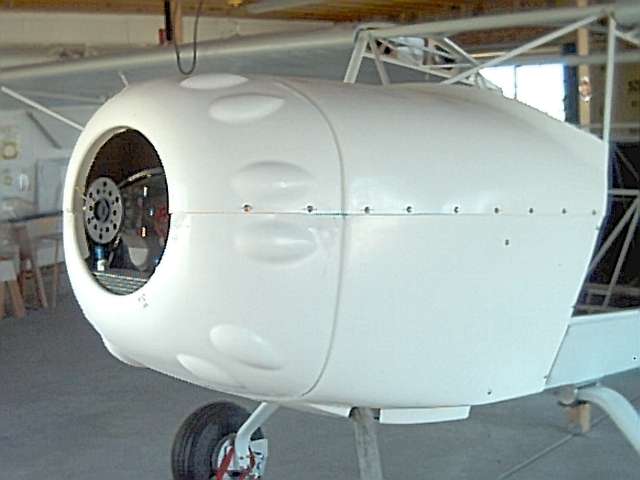
Cowl
The cowl was fitted over the engine. A hole in the bottom of the cowl was cut for the exhaust pipe. I goofed, put the hole in the wrong location, and had to oversize it to fit the pipe. Now I will get to try my skill at fiberglass repair.
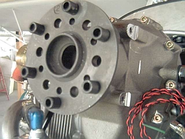
The prop mounting flange required some inserts to be pressed into place. These threaded inserts take most of the load as the engine drives the prop. They also provide the place for the bolts to attach. The inserts were not initially provided by either Skystar or Rotax.
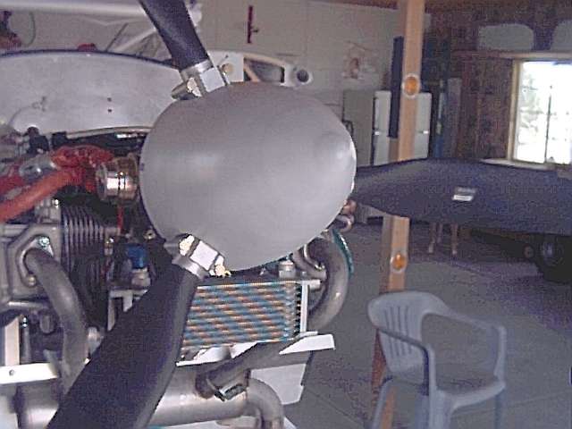
The three bladed Warp Drive composite propeller was mounted between the two halves of its clamshell hub and the initial blade angle was set. The blades are adjustable so they can take a user defined 'bite' out of the air. My initial setup is a pitch of 25 degrees measured at the inboard edge of the nickel leading edge protection.
The aluminum spinner was trimmed around the prop blades and attached with screws and nutplates to the spinner flange.
Once mounted, all the engine controls and wires had to be routed through the firewall and into the cockpit. This included throttle cables and choke cables to each (of two) carburetors.
Cowl Trimming
The round cowl blocked most of the frontal area of the oil cooler. During flight testing, the oil temperature was hotter than I wanted, so I decided to improve the airflow over the cooler. I trimmed out the bottom cowl so that the entire oil cooler was exposed to the incoming air. I then reconstructed the rounded cowl lip with fiberglass.
 Builder's Log - Engine Installation