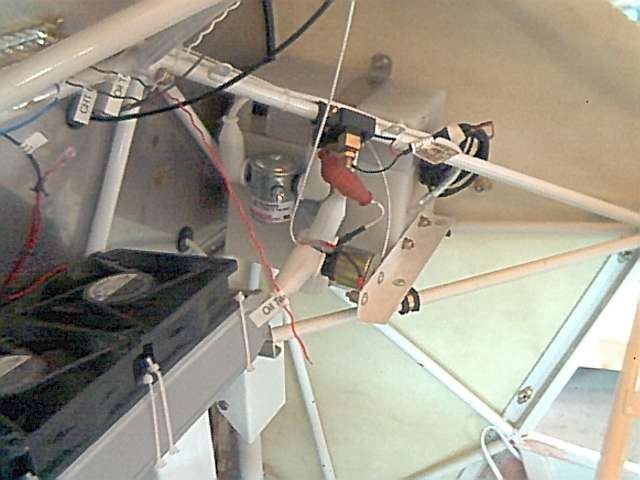
The battery is mounted behind the panel above the passenger's knees. It is housed in a plastic box which is attached to structural tubing. The master solenoid (silver) is mounted on the box. The starter solenoid (brass) is mounted next to the battery box. This keeps the cable runs short.
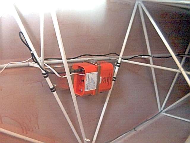
Emergency Locator Transmitter
The emergency locator transmitter (ELT) is attached to structural tubing behind the passenger seat. It is powered by six 'D' cell alkaline batteries.
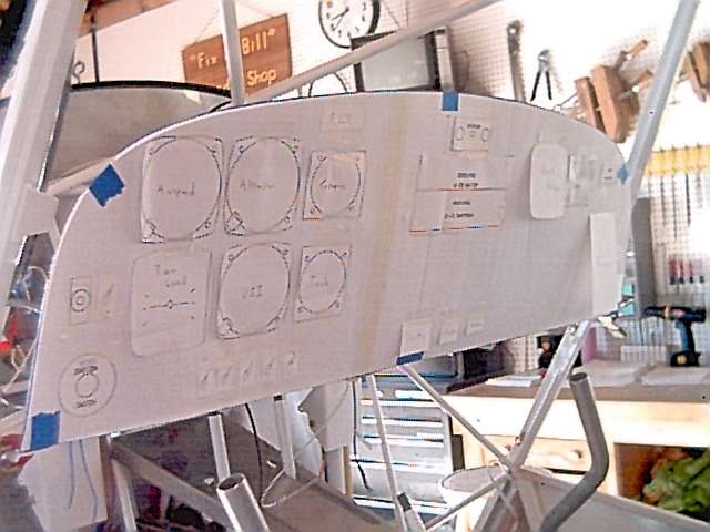
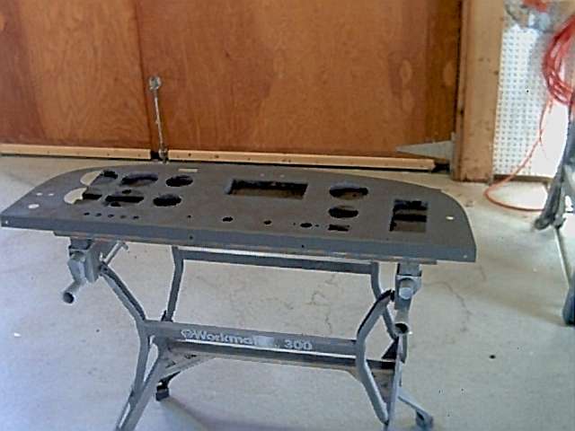
The instrument panel is built on an expensive piece of aluminum. Prior to cutting and drilling this piece, I needed to figure out where everything was going to fit. I used paper cutouts to arrange everything, taped them in place, and kept at it until I was satisfied with the results.
Panel Fabrication
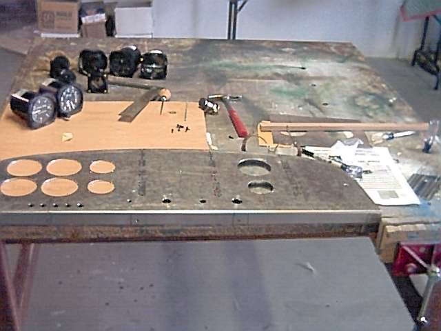
After careful marking, the holes were cut in the panel. Large circles were made with a fly-cutter in a drill press. Smaller circles were made with a unibit. Rectanglular holes were cut with the Dremel tool and plenty of cuttoff disks.
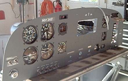
The panel was painted. It will be populated prior to installation in the cockpit.
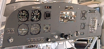
The panel was labeled with white laminated lettering. Switches and instruments are installed. As much of the wiring as possible is completed while the panel is still on the work bench.
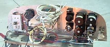
I purchased a communication radio, transponder, and intercom and had the avionics shop prepare the wiring harness for me. As you can see by the spaghetti behind the panel, there are alot of wires - even for a simple VFR installation.
Grounding
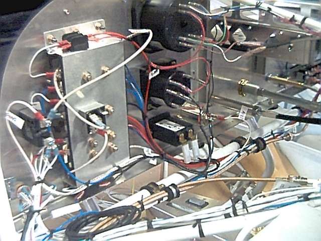
All of the system's ground wires run to the grounding block pictured here. It is mounted on the inside of the firewall. Fast-On terminals are used to make the connection.
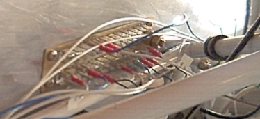
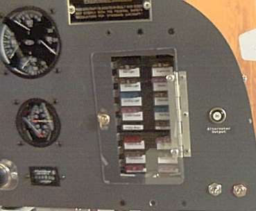
I chose not to use glass tube fuses or traditional aircraft circuit breakers for the majority of the electrical wiring protection. I have used fuse blocks which hold spade type fuses like those used in an automobile. Wire connections to these fuse blocks is a 1/4 inch fast-on clip. I wanted the fuses accessible from the cockpit, so I made the recessed mounting bracket shown here, cut the panel for access, and covered the fuse blocks with a polycarbonate hinged door.
The electrical system was designed after attending a seminar with Bob Nuckolls (AeroElectric Connection). He explained his concept of a main bus and an essential bus. The essential bus contains those items that would be the most essential for safe completion of a flight in the event an alternator failed and the reserve in the (very small) battery was the only remaining source of power. My essential bus powers the cabin light, comm radio, transponder, and turn coordinator. It gets power through the main bus (routed through the square diode attached to the mounting bracket back) whenever the master is on. In the event that the alternator fails, I can shut off the master and energize the essential bus with a switch directly from the battery. Power will not pass back to the main bus since the diode acts as a one way traffic cop. Remaining battery power is conserved by de-energizing all nonessential items - including the 1 amp or so normally needed just to keep the battery solenoid closed.
Panel Installed
The panel was mounted in the cockpit and all the other items were hooked up. This included all the cables, engine instrument leads, and ignition wires.
 Builder's Log - Instrument Panel