The wings came partially assembled as part of the quick build option. The spars were already mounted within the wing ribs. Most of the false ribs were attached. Primary construction duties in this phase of the project consist of attaching mounting hardware and mounting the wings (with struts) to the fuselage.
I built two large trestles (sawhorses) to support the wing while it was being worked on. I also built a rotating wing stand which allows me to mount a wing at any angle of rotation for construction.
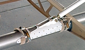
Several pieces of hardware had to be fabricated and prepared prior to wing installation. Pictured here is one of four attach brackets which connect the lift struts to the spar. As you can see, there were a lot of rivet holes to drill in each bracket. This was complicated by the fact that the bracket was round and difficult to maneuver in the drill press. Skystar suggested that I tape the bracket over a piece of PVC pipe for ease in handling. It helped.
Some curved steel stock was provided in the kit to fabricate doublers for those points where the spar tubes will attach to the fuselage. These doublers were built and primed.
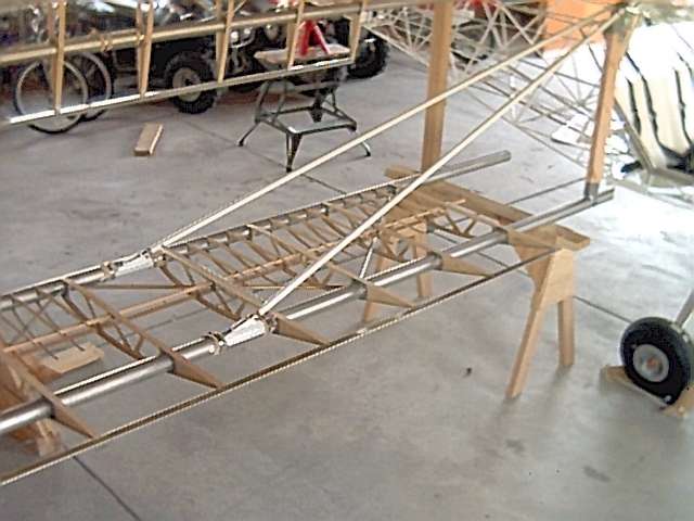
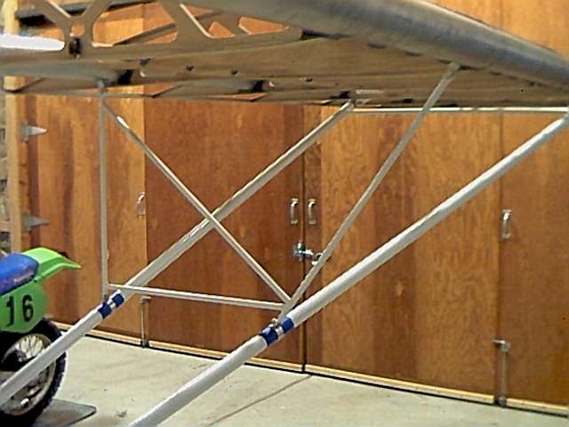
The lift struts were attached to the spars while the wings were resting upside down on the trestles. At this point, the attach brackets are temporarily attached with hose clamps. This will allow me to properly adjust the wing position as I fine tune the rigging. A temporary brace of 2x4 was taped in position to help keep the lift strut in alignment. All mounting points have been reamed to proper dimensions, a relief cut was made in the rear spar to allow the wing to pivot and fold, and the wing is ready for initial installation.
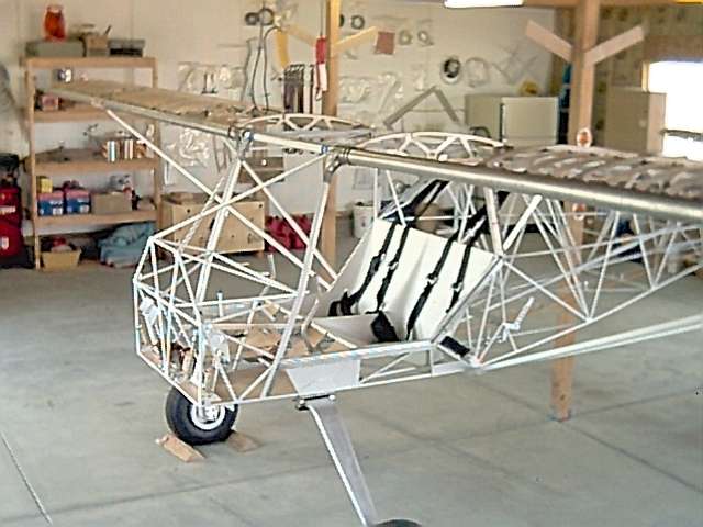
Both wings have been initially attached. This was a two person job as the wings were a bit heavy and unwieldy for one. The placement must be carefully measured for proper wing sweep, dihedral, twist, and alignment before the final mounting holes are drilled.
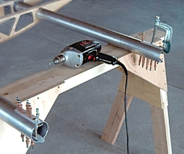
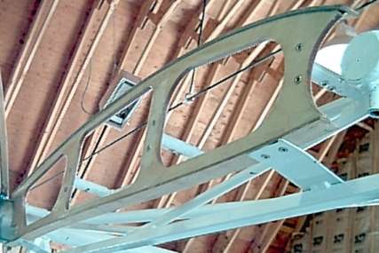
The wings were carefully aligned and the final spar attach holes drilled. These holes require reinforcement with steel brackets due to the load that they will ultimately support. The steel tabs were formed, primed, match drilled, and fastened with epoxy and rivets. Air temperature on this day was above 90 degrees, so the epoxy had a tendency to set very quickly.
Once all spar reinforcement was completed, the wings were reattached to the fuselage. Jury struts, which bridge the lift strut to the spar, were placed. This step required eight steel brackets to be fabricated and attached to the spars.
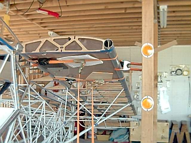
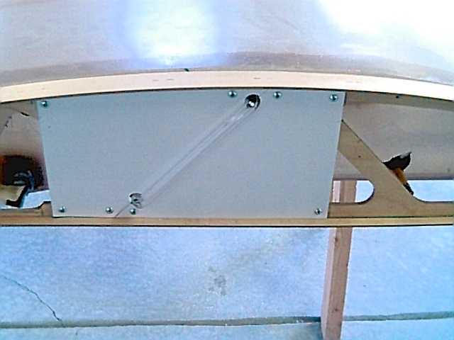
The gas tanks were installed between the spars using a silicon based adhesive. All the fittings in the tank were sealed with Permatex #9. The fuel sight tubes were formed and cut to fit.
The partial rib and the false ribs were epoxied to the underside of the fuel tanks.
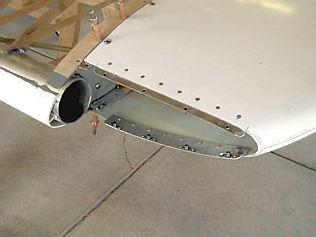
Trailing Edge
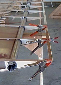
The aluminum trailing edge was placed behind the gas tanks. This strip was attached with epoxy and rivets. It will provide a rigid surface for the fabric attachment.
Fuel Tank Sight Tube
Fuel level is determined from inside the cockpit by observing the level in a sight tube. The tube was fabricated out of plastic and installed in the tank fittings.
Flaperon Assembly
The flaperons are the control surfaces which control roll. During fabrication, I riveted the trailing edge with my hand rivet squeezer.
The outside tip of the flaperon was given a rounded profile by shaping foam and coating it with structural epoxy. The inside tip is where the control horn was attached. Mass balance wieghts were attached to overcome any tendency for aerodynamic flutter.
Wingtips
The wingtips are made of fiberglass. They were cut to fit and made removable by the intallation of a metal flange as an attach point. The tips are secured to the wing with screws which attach to nutplates mounted on the flange.
A landing light is being installed inn the left wingtip. The leading edge of the tip was removed to accomodate a lens. The light bracket resides inside the wing tip.
Navigation lights and strobe lights are located on the end of the wingtip. A fiberglass blister was attached to provide a mounting surface.
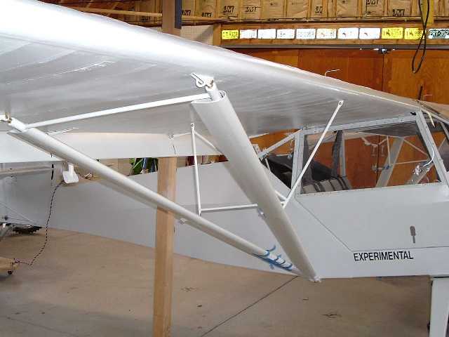
Speed Fairings
After the first 20 hours of flight testing, I decided to add the PVC fairings to the lift struts. Their purpose is to streamline the round tubing and reduce drag. Installation consisted of trimming, glue application, and snapping into place.
The fairings resulted in about 8 mph increase in speed!
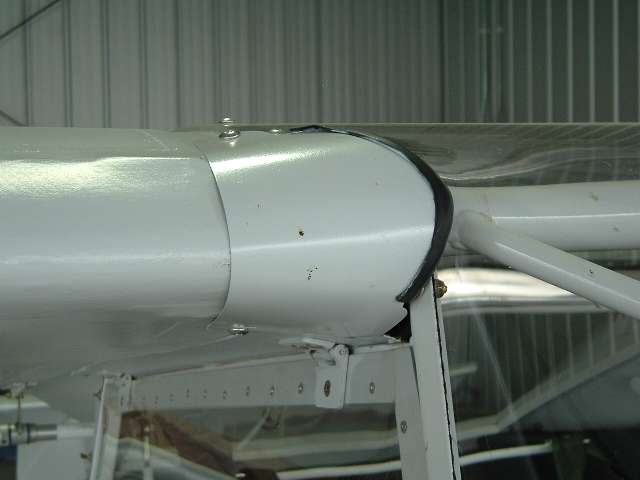
Wing Root Covers
The junction of the wing root and the windshield was finally covered at 100 hours. It really smoothes the transition. Why did it take me so long? I guess that I was having too much fun flying to take the time for the remaining cosmetic touches.
 Builder's Log - Wing Assembly